
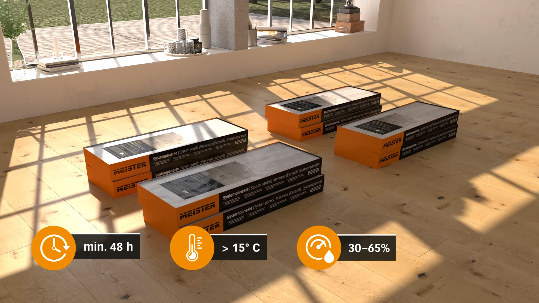
It is important to acclimatise the panels before laying them. Store them unopened for approx. 48 hours in the centre of the room in which you want to lay them. The room temperature must be approx. 20°C (at least 15°C), and the relative humidity must be approx. 30–65%.
Make sure that the walls and ceilings are dry, i.e. contain a maximum residual moisture of 5%.
As the panels are only suitable for indoor use, you should refrain from using them in home conservatories or skylight linings due to high incidence of sunlight and the associated temperature fluctuations.
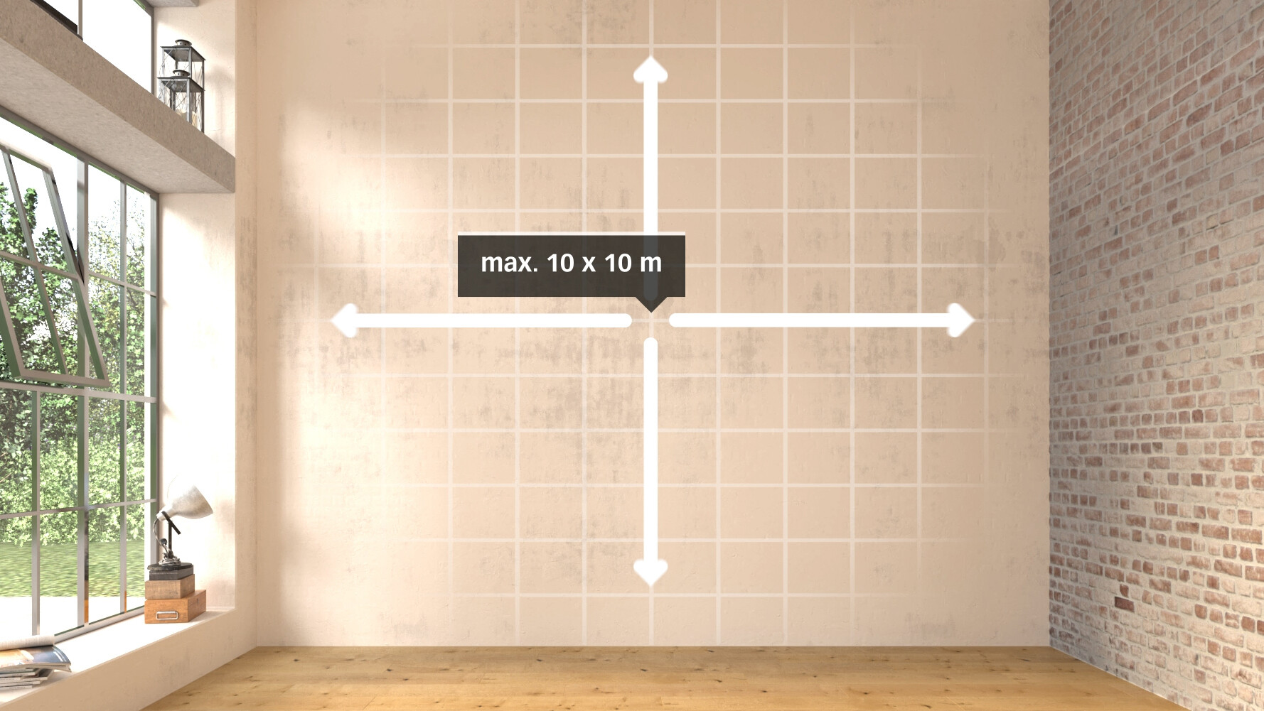
You need an expansion joint if your installation surface is longer or wider than 10 metres. This should be covered with border moulding in matching colours. It is also important during installation that you allow a gap of at least 10–14 mm next to all walls and other fixed elements.
During installation, make sure that air can also circulate behind the wood panelling (possibly provide batten backing structure). It is important to avoid trapped air!
MeisterPanels. nova are also suitable for laying in humid rooms, although they are not suitable for use in areas directly exposed to splashing water (such as showers or home swimming pools). It is essential to ensure air can circulate behind the wood panelling! When working in humid rooms, only use assembly parts that are protected against corrosion.
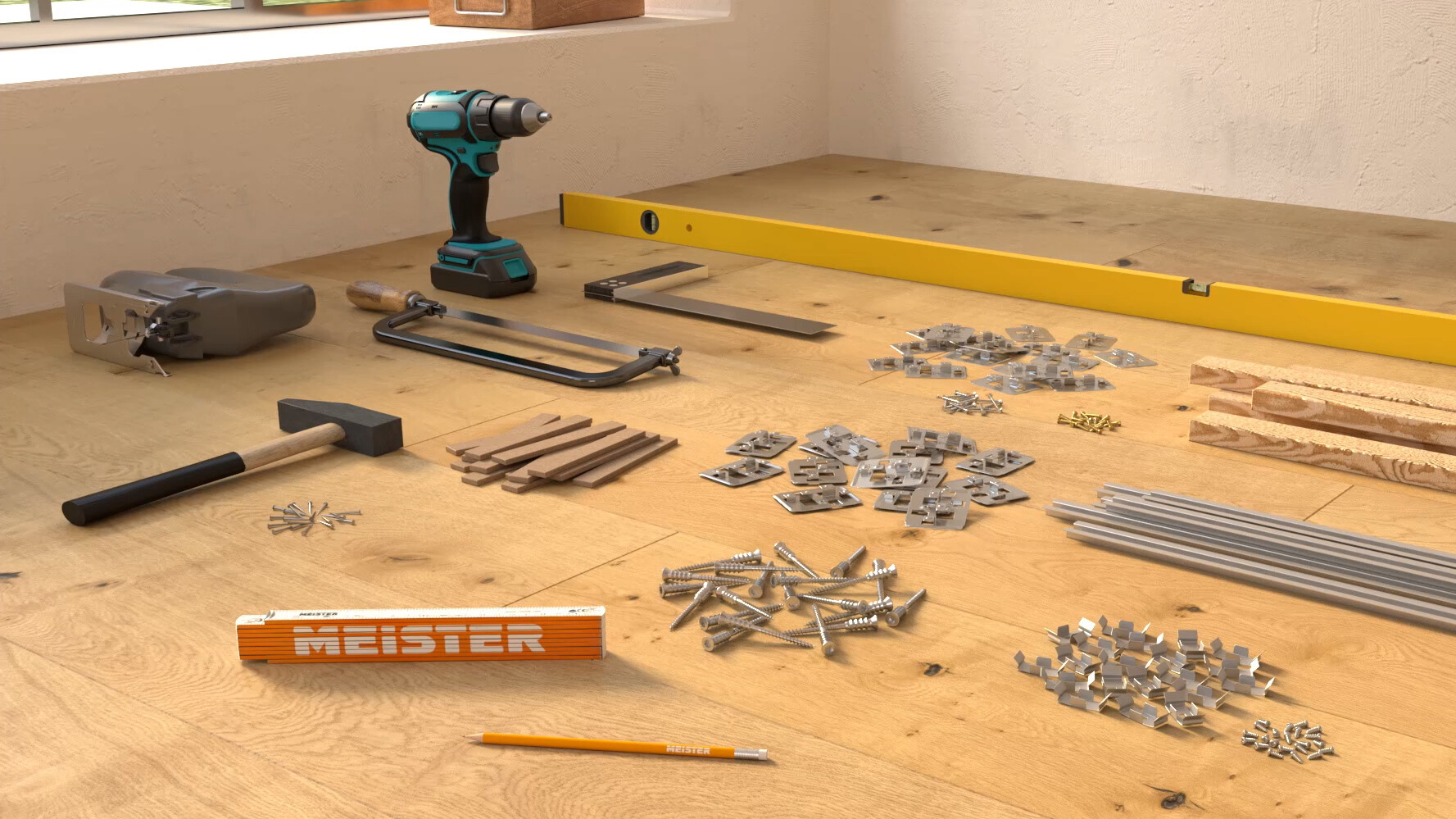
Fixing material:
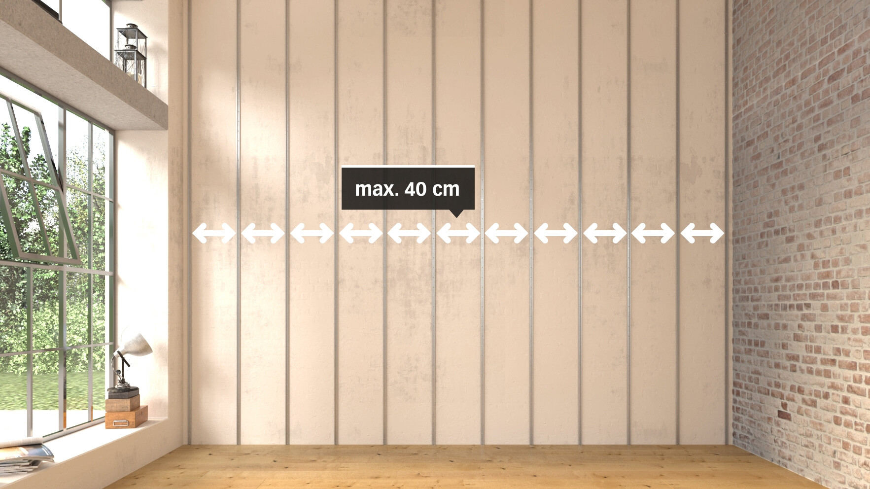
Place the Type 8 batten profile at maximum intervals of 40 cm apart. The profile is mounted crossways to the panel length and fixed so that there is an even sub-structure.
Please use suitable plugs or screws to screw the sub-structure to the raw ceiling or wall at intervals of 40–50 cm. Correct any slight unevenness in the wall/ceiling by placing spacers or wooden wedges underneath the laths. Use a standard metal hacksaw or one-hand angle grinder with metal cutting disc to trim the profile.
A minimum gap of 20 mm is required when installing MEISTER recessed lights (the use of recessed lights is only permitted with MeisterPanels. nova SP 300). The required gap must be ensured using a spacer of at least 12 mm attached to the wall/ceiling.
To avoid damaging the surface, be sure to note the following when sawing the elements: The decorative side should be face up when using a bench saw or face down when using a jigsaw or hand-held circular saw.
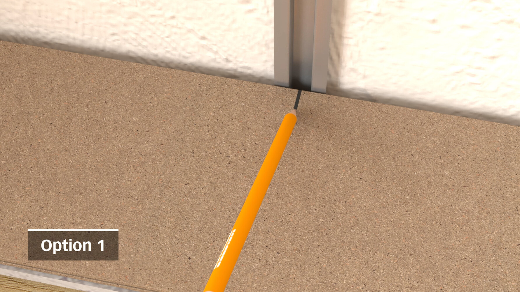
When installing on the Type 8 batten profile, install the start/end clip and the spacer on the back of the first row of panels.
The row of panels is placed on the sub-structure (rail). The middle of the rail is marked using a pencil. Once this measurement has been transferred to the back, fix the start/end clip to the back of the panel with a gap of 2 cm to the outside edge using the supplied screws. The screws have to be fixed in the middle of the cut-out to allow for any inaccuracies to be corrected. Tighten the screws but do not overtighten them.
If the clip does not slot in correctly then the profile may have been compressed during trimming. In this case, please bend open the profile to its original dimensions again so that the start/end clip can be clearly heard clicking in.
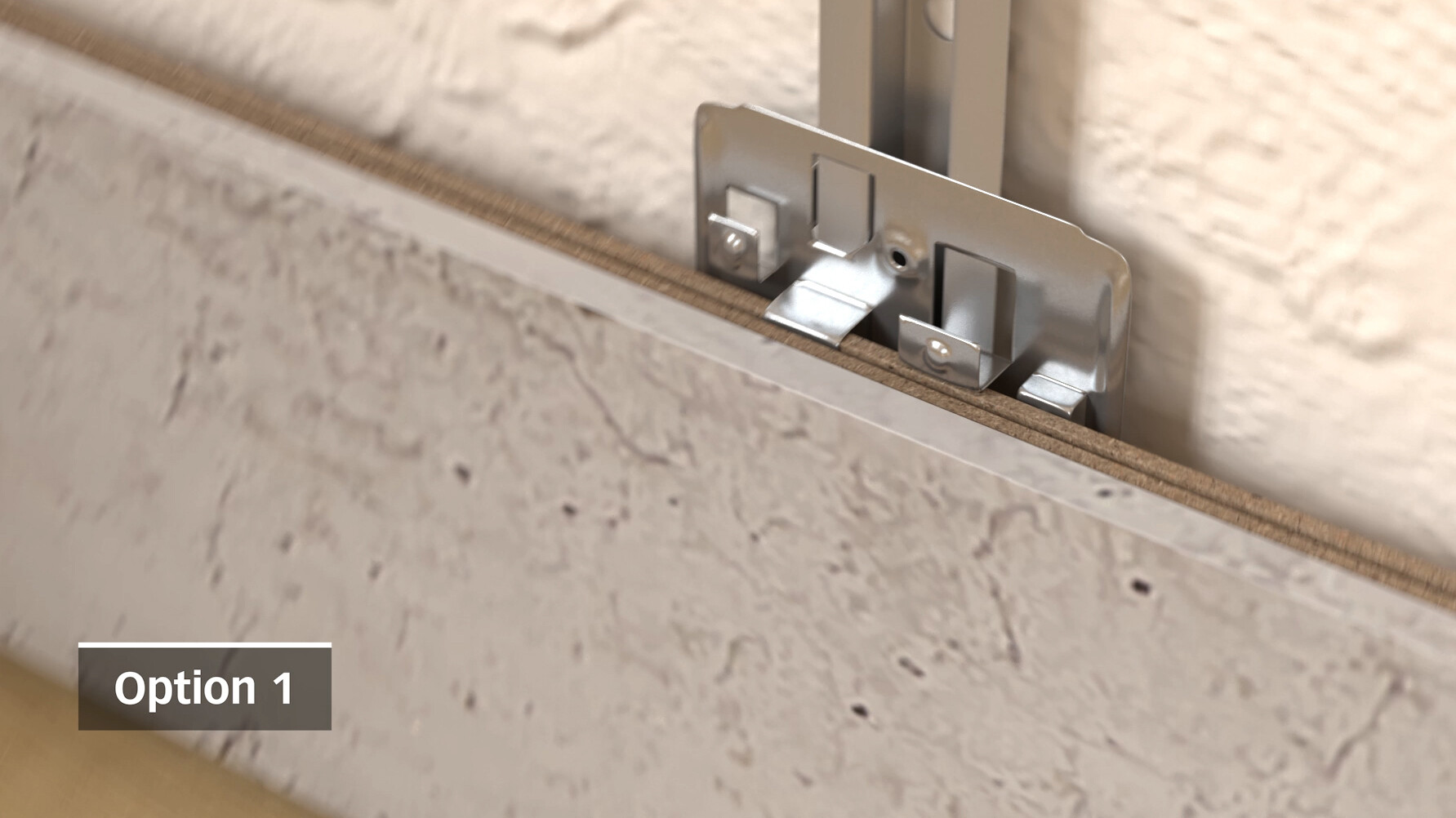
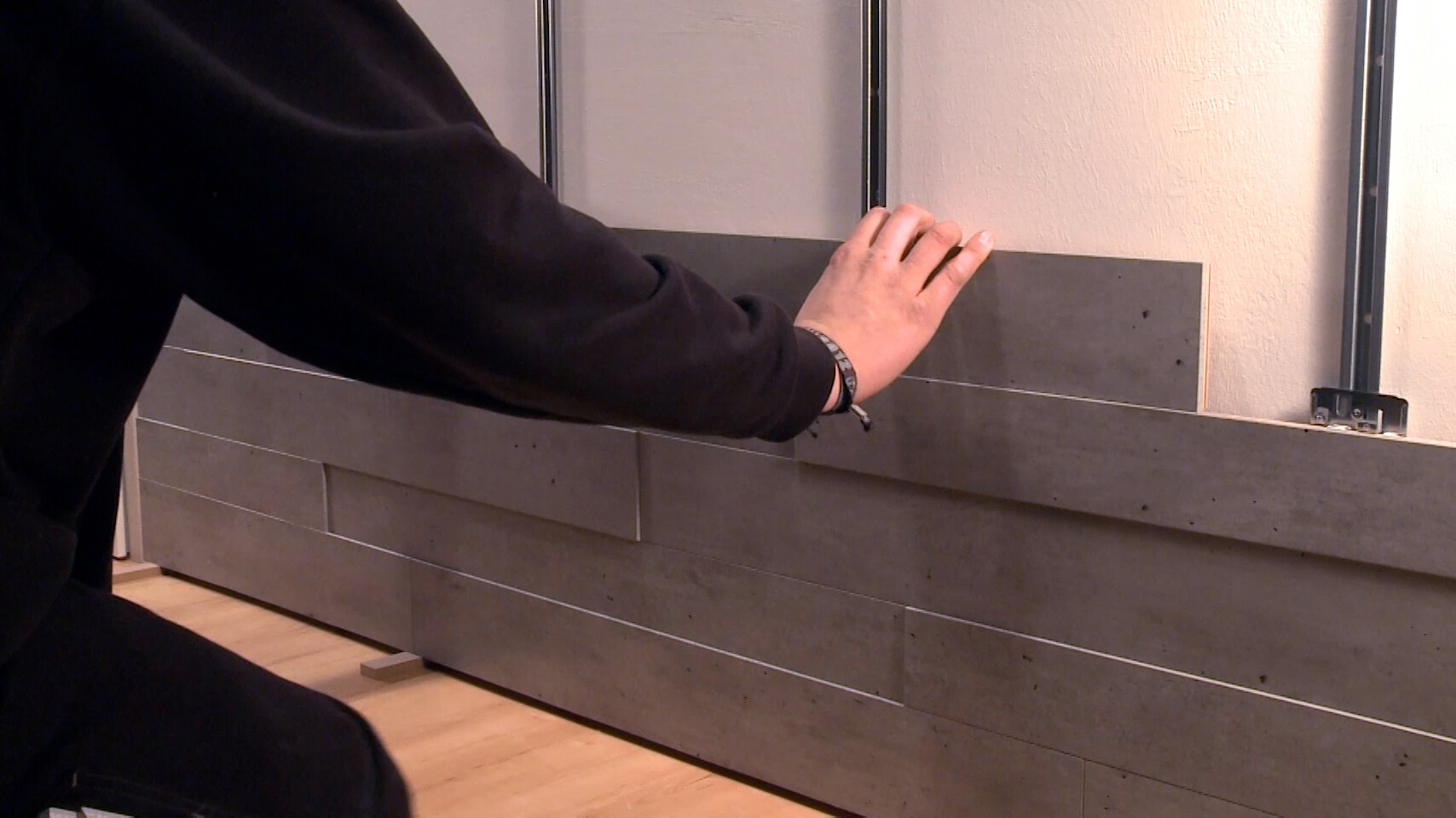
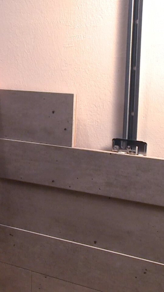
Screw the TOP 300 M clips for the first row onto the profile then push into panel groove 1 and lock. Having aligned the first row of panels, fix the fixing clips with screws or rivets to prevent them being displaced during the rest of the installation.
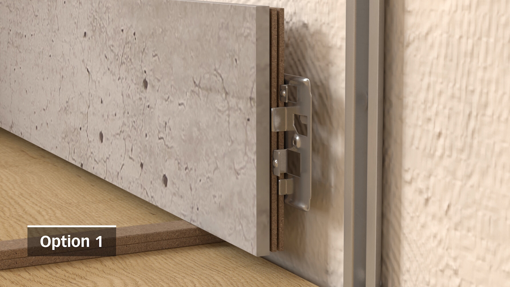
You can change the depth of each panel individually by inserting it into the first or second groove, thereby creating the desired 3D effect. Be sure to maintain an offset of at least 15 cm at the head joints. The TOP 300 M clips must also be used at all head joints. If there is no sub-structure at this point, the TOP 300 M is simply pushed into place.
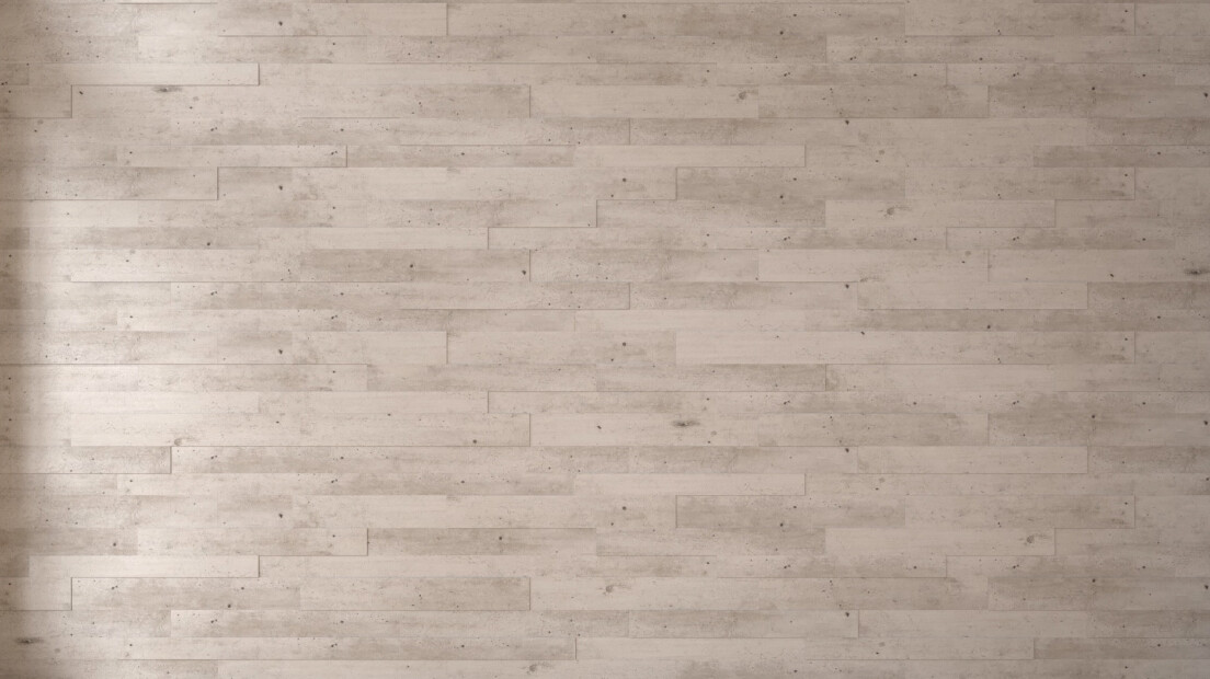
Each pack contains panel boards in three different widths; lay each row ‘continuously’ in a different width. Continue laying row by row in this way. Trim the panels so that there is at least a 10–14 mm gap to the wall. Pre-installing several TOP 300 M clips on the profile speeds up the installation of the subsequent panels. The last row of panels can be mounted like the first one using the start/end clip.
Start with the sub-structure, installing dry battens planed on one side if possible with a minimum cross-section of 20×40 mm. The battens should be spaced no more than 40 cm apart. The battens must be installed crossways to the panel length and fixed so that there is an even sub-structure.
Please use suitable plugs or screws to screw the sub-structure to the raw ceiling or wall at intervals of 40–50 cm. Correct any slight unevenness in the wall/ceiling by placing small wooden wedges underneath the battens.
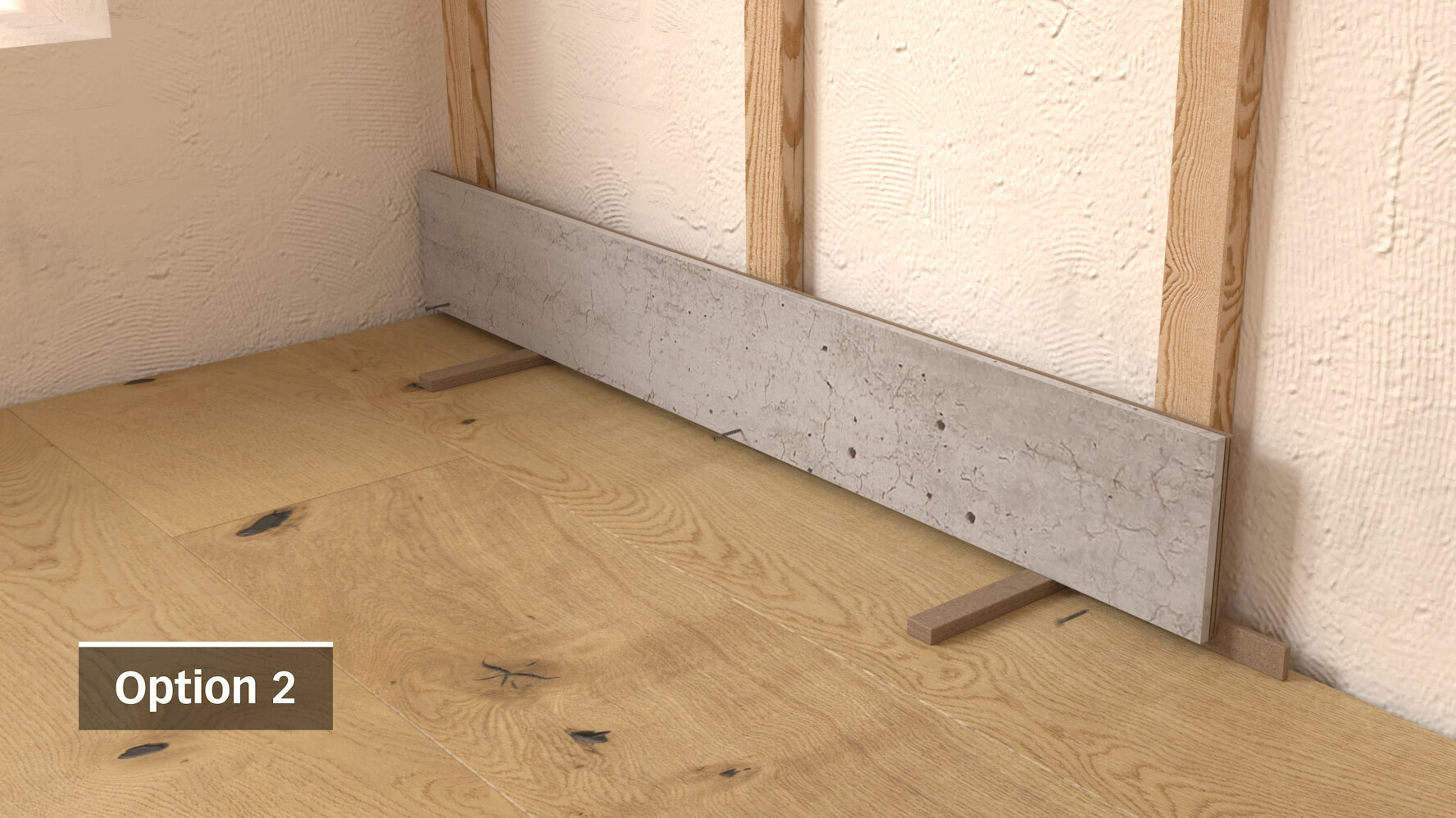
When mounting on wooden battens, place the enclosed spacers on the back of the first row of panels and screw or nail them down so that they are ultimately covered by the ceiling finish or angled cover moulding. Now slide the TOP 300 H clip into longitudinal groove 1. The first row should protrude 4 mm all the way along.
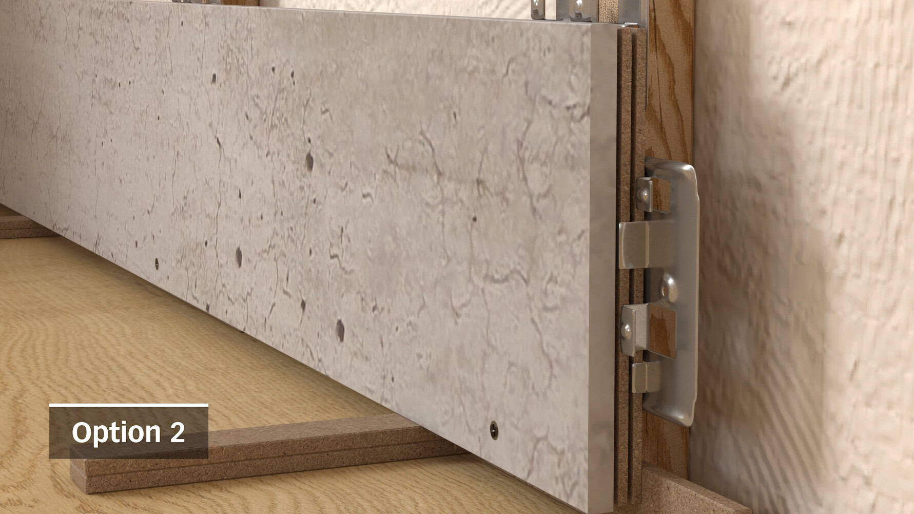
You can change the depth of each panel individually during the course of the installation process by inserting it into the first or second groove, thereby creating the desired 3D effect. Be sure to maintain an offset of at least 15 cm at the head joints. The TOP 300 H clips must also be used at all head joints. If there is no sub-structure at this point, the TOP 300 M clip is simply pushed into place rather than being screwed in.

Each pack contains panel boards in three different widths. Lay each row ‘continuously’ in a different width. Continue laying row by row in this way. Trim the panels so that there is at least a 10–14 mm gap to the wall. When installing the last row, proceed in the same way as for the first.
The double groove and different widths of the panel boards facilitate a wide range of designs and patterns.
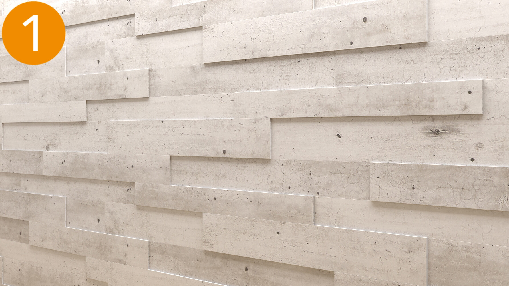
The 3D effect is achieved thanks to the double groove on the individual elements. By inserting the panel boards alternately into the first or second groove, the panels can be installed offset to create an attractive vibrant effect.
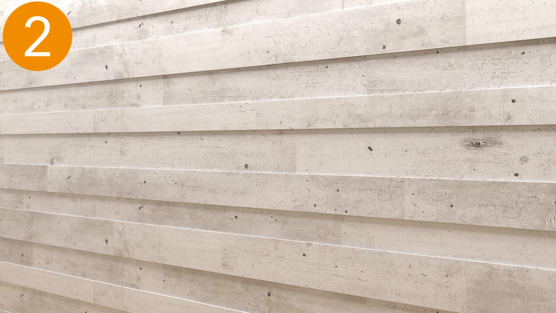
Laying in rows is equally vibrant but somewhat neater. Here, the different widths are each laid in rows at an even level and in the same groove.
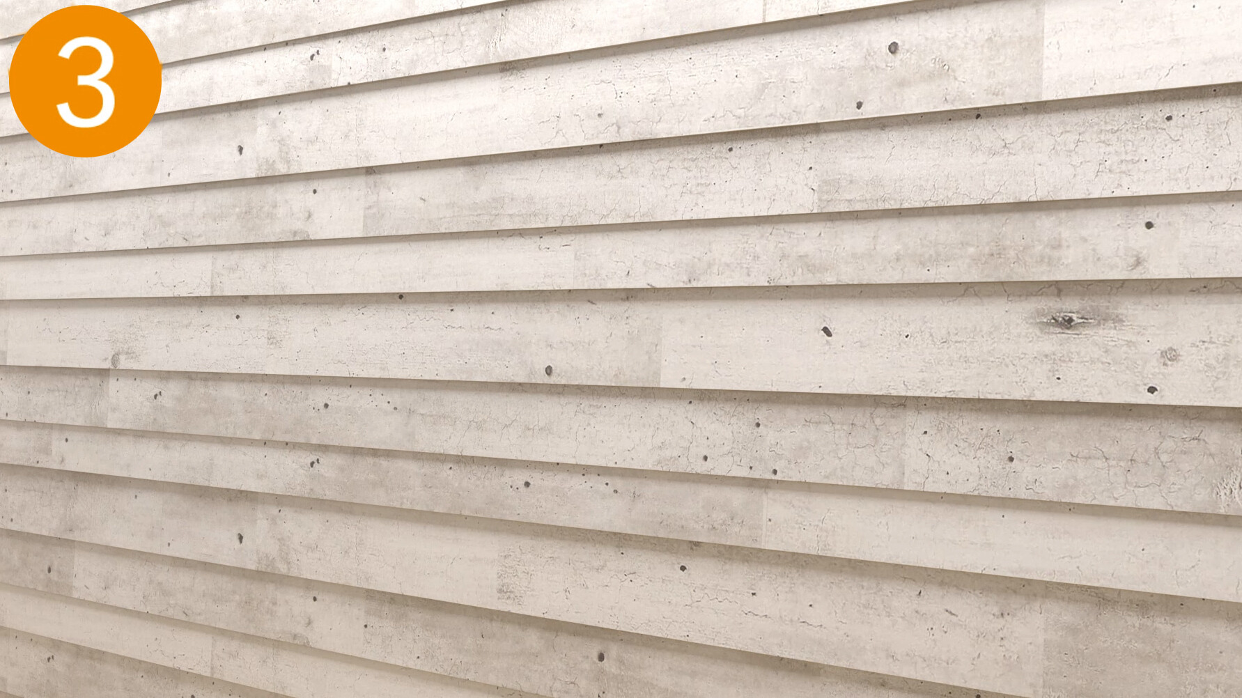
To create this effect, the lower side of the panel board is pushed forward slightly so that it sits on the front plane of the clip. The upper side of the panel is fixed flat to the batten profile. This creates a striking visual effect.
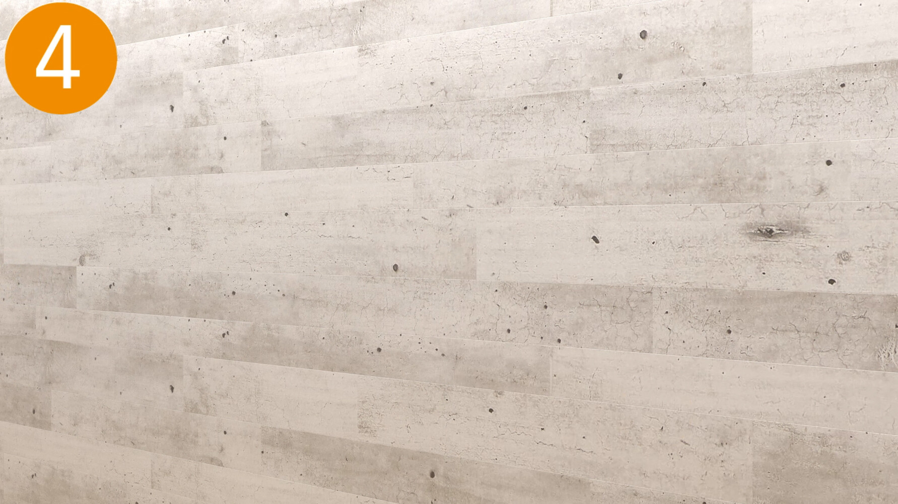
Fans of having things level and even can install all of their MEISTER system panels at the same level by always using the same groove. This means there is no offset, resulting in a very uniform surface.
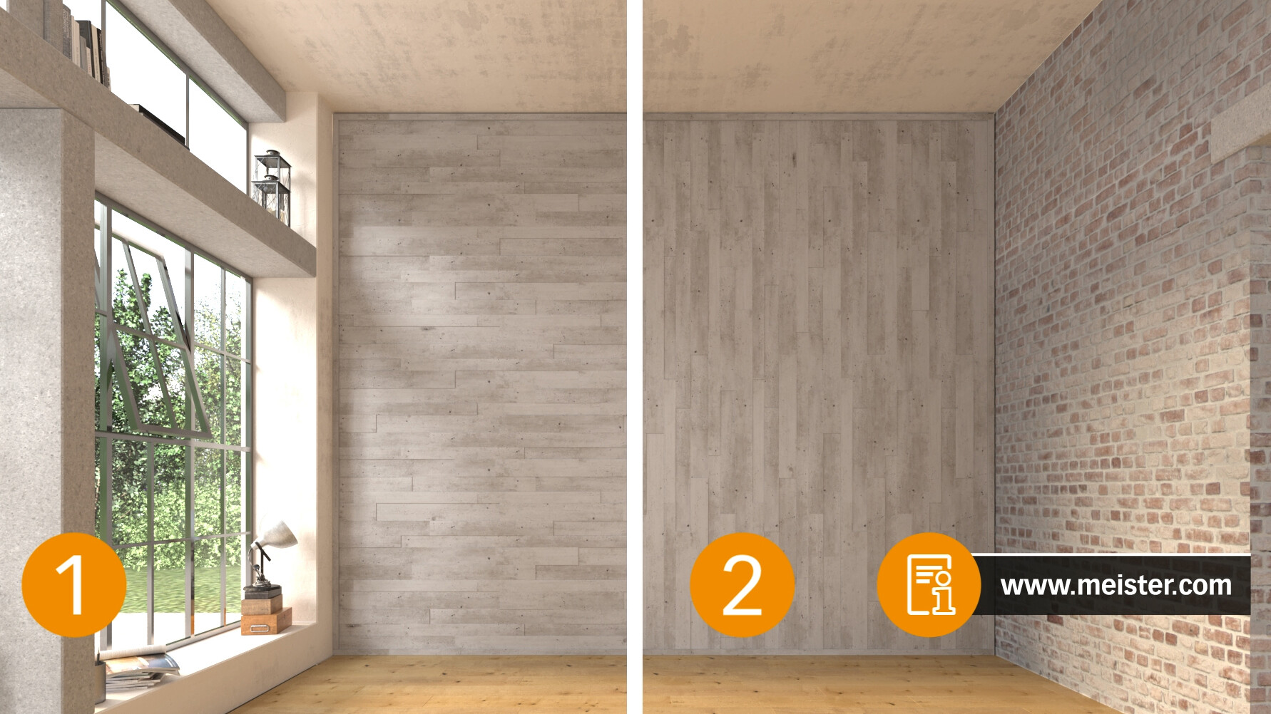
But regardless of which arrangement you go for, all of them can be laid either horizontally or vertically!